")
What does latency mean in terms of video technology?
When transferring digital content from a medium to a display, a certain latency is always to be expected. This refers to the time that elapses between sending a signal or recording an image and displaying the respective content on the screen. The reason for this delay lies in the different processing stages, which require a short-term storage of the data to be transmitted.
Latency is always expressed in time units, for example in seconds or milliseconds. There is no universal value that defines a low or high latency. What is considered acceptable latency varies depending on the scenario and application. For a PowerPoint presentation, for example, low latency is generally not essential. Whether the audience can see the next slide on the screen immediately after the presenter has pressed the button on his remote control or after a delay of one second, is not very important in this specific case.
However, the situation is different when live images are displayed on a LED wall – for example those of a concert. In this scenario, the image is sent to the LED wall while the sound is sent to the speakers. If there is a difference in processing times, i.e. different latencies, the two signals are output offset and lip sync is broken. This can have an irritating effect on the audience.
Therefore, the design goal for any system dealing with real-time interaction with the video content should be low latency.
How tolerant are we of such audio-visual asynchrony? Or in other words: How large must the image/sound offset be for us to notice it?
The conversion of single frames into time depends on the frame rate of the video. From about 14 to 16 frames per second (fps), the human brain perceives successive images as moving. A higher frame rate ensures smooth perception. With the introduction of sound film, this frequency was set at 24 fps.
Nowadays, significantly higher frame rates are possible, 50 fps and more are even common for many applications. If in this case the display on the LED screen is delayed by exactly one frame, this corresponds to a latency of 1/50 second or 20 milliseconds.
According to a recommendation of the European Broadcasting Union, the offset should not be more than 40 ms before or 60 ms after the actual synchronization point in order to maintain lip sync. For video content with a frame rate of 50 fps, the noticeability of asynchronicity thus begins at an offset of two to three frames.
What is the relative latency of a LED wall?
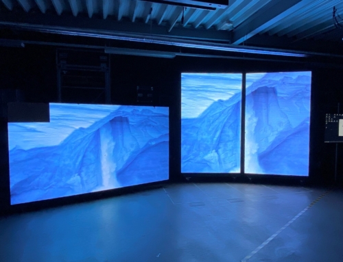
We want to put our LED systems to the test and determine the relative latencies of different component and setting combinations. To do this, we are testing the interaction of our sending and receiving cards with the configuration options that we can make with the controller software.
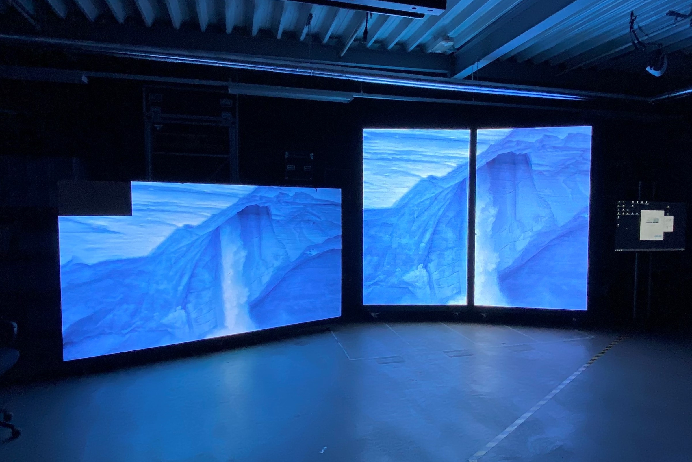
The structure for our test series is as follows: An iPad with a refresh rate of 60 Hz is connected to two LED walls via a HDMI splitter and two different controllers. On the iPad we run a stopwatch with millisecond display. At 60 Hz, 16.7 ms corresponds to one frame – this means that every 16.7 ms a new image is displayed on the LED wall.
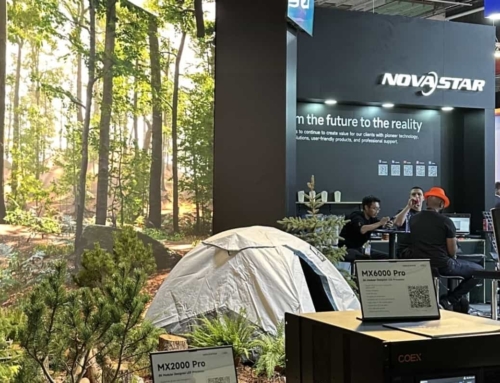
The iPad sends the signal via HDMI to a splitter, which in turn distributes it to the NovaStar controllers, which finally control the LED modules via network cables. In order to detect differences between the respective hardware combinations and their settings, we film the screens with a high-speed camera and compare the material afterwards.

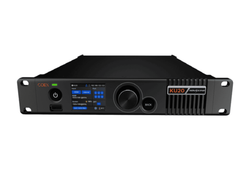
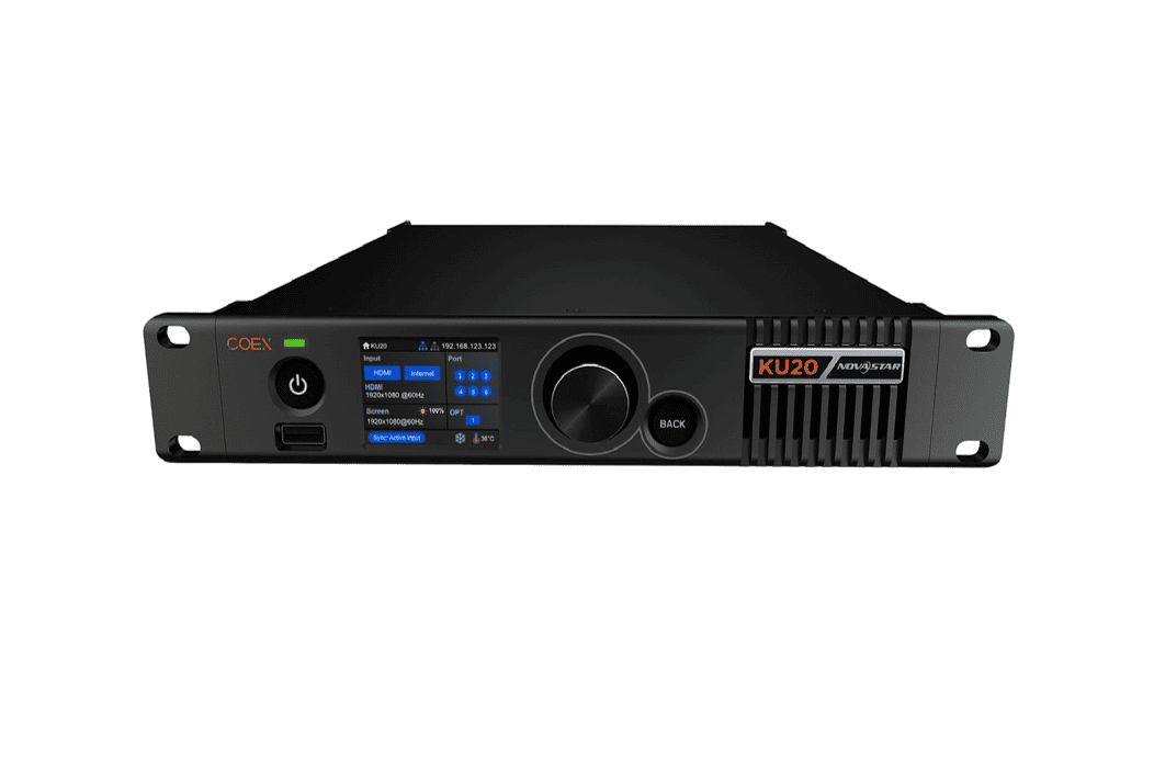
NovaStar MCTRL660; Source: LedTek (E)

Test setup; Source: LedTek (E)
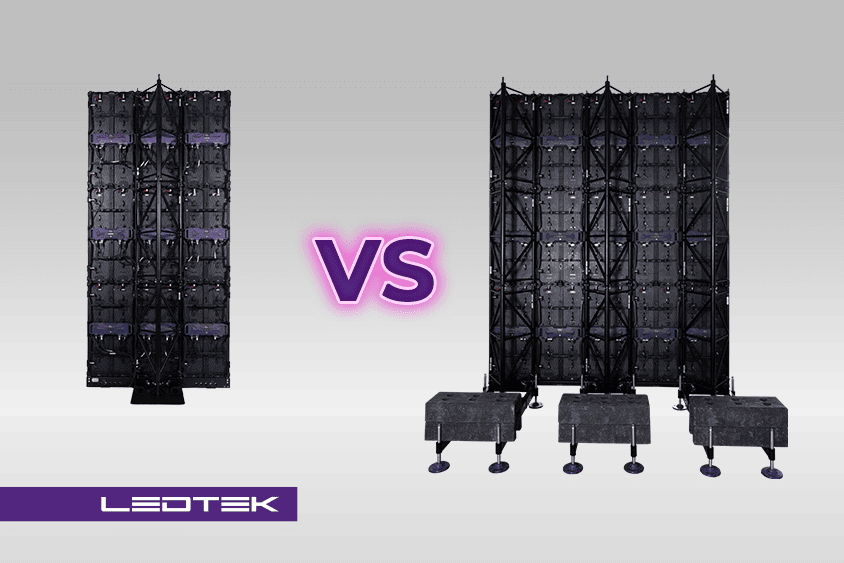
In our experiment we are testing two LED walls in combination with different controllers: The P2+sBL, which like our Pro series uses an A8s receiver card with low latency function, and the P3+sBL with a MRV-210 card and without such a mode. The following NovaStar controllers are used:
Sending cards: MCTRL4K, MCTRL660, MCTRL300
All-in-One Controller: NovaPro UHD, NovaPro UHD Jr, VX4S, VX6S
Media player with scaler function: Taurus TB6
The low-latency mode
NovaStar products are designed to enable low latency in the transmission of digital content. Many of the devices also feature a so-called low-latency mode (LLM), which reduces the latency up to 2 frames. These include, for example, the MCTRL4K and UHD controllers and the Armor series receiving cards.
This mode can be switched on for both sending and receiving cards via the NovaLCT interface, which is used to program the LED wall.

NovaLCT – low-latency mode; Source: LedTek (E)
Even if – as is the case with our P3+sBL – a receiving card without LLM support is used, it is still advisable to switch on the mode for the controller’s sending card. This way the latency can be reduced by about 1 frame.
In any case, you have to pay attention to the wiring of the wall: the wired area may measure a maximum of 512 pixels wide for the LLM to work.
Let’s assume a 3 x 4 meter wall of P3 modules. Four of these modules side by side result in 512 pixels in width. A data cable for the P3 can serve 10 m². If we didn’t want to use the low-latency mode, we could wire like this:

If the LLM is to be used, we would have to proceed as follows because of the limited width:

NovaLCT – Module cabling; Source: LedTek (E)
Setting a reference value
We want to find out how big the difference between the low-latency devices and the hardware without this feature is. To establish a reference value, we needed to make sure that our test setup works smoothly and synchronously. In order to achieve this, we used our fastest hardware: A P2+sBL with MCTRL4K controller and both sending and receiving cards running in low-latency mode. We set up an iPad which played a millisecond timer, which again was distributed via a HDMI splitter to two identical MCTRL4K controllers and output by them to two identical P2+sBL modules. Our test showed that the two screens run exactly synchronized.
Watch the video at the end of this article to get a closer look at the experimental setup.
Test series
In our test series, we will now focus on the various combination and setting options of our hardware. It should be remembered once again that our two LED modules have different receiving cards. The P2+sBL uses the A8s, which comes with LLM. The P3+sBL, on the other hand, uses a MRV-210 card, which works without this mode. For testing the P3, we only have the option to activate the LLM for the controller’s sending card.
Test #1: MCTRL4K
| module | LLM sending card | LLM receiving card | latency |
|---|---|---|---|
| P2+sBL | off | off | 29 ms (approx. 1.5 frames) |
| P2+sBL | on | off | 17 ms (approx. 1 frame) |
| P2+sBL | off | on | 12 ms (< 1 frame) |
| P2+sBL | on | on | 0 ms |
| P3+sBL | off | not existing | 30 ms (approx. 2 frames) |
| P3+sBL | on | not existing | 17 ms (1 frame) |
The MCTRL4K is our fastest controller in combination with the P2 and serves as a reference for the other test series. If the LLM is only switched on at the sending card, the P2 and the P3 are equally fast. If we add the LLM of the P2 receiver, the difference is 1 frame.
The difference between the fastest possible constellation (LLM switched on at transmitter and receiver) and the slowest (both off) is 2 frames.
Test #2: UHD Jr
| module | LLM sending card | LLM receiving card | latency |
|---|---|---|---|
| P2+sBL | on | on | 16-26 ms (approx. 1 frame) |
| P2+sBL | off | off | 46-53 ms (approx. 3 frames) |
| P2+sBL | off | on | 30-45 ms (approx. 2 frames) |
| P2+sBL | on | off | 32-46 ms (approx. 2 frames) |
| P3+sBL | off | not existing | 49-56 ms (approx. 3.5 frames) |
| P3+sBL | on | not existing | 40-47 ms (approx. 2.5 frames) |
The result is very similar for the UHD Jr: No significant difference without low-latency mode at the module and about 1 frame difference with active LLM at the P2. The somewhat less accurate results are due to the FPGA boards that are not working one hundred percent constantly and are built into the scalers. The UHD Jr is about 1.5 frames slower than the 4K sending cards.
Attention! For the UHD Jr, LLM must be switched on at the device. Activation via the NovaLCT software does not result in an error message, but the settings will not be applied (as of September 4, 2020).
Test #3: UHD (2K-HDMI)
| module | LLM sending card | LLM receiving card | latency |
|---|---|---|---|
| P2+sBL | on | on | 25-36 ms (approx. 2 frames) |
| P2+sBL | off | off | 61-67 ms (approx. 4 frames) |
| P2+sBL | off | on | 44-53 ms (approx. 3 frames) |
| P2+sBL | on | off | 40-57 ms (approx. 3 frames) |
| P3+sBL | off | not existing | 61-67 ms (approx. 4 frames) |
| P3+sBL | on | not existing | 40-57 ms (approx. 3 frames) |
Test #4: UHD (4K-HDMI)
| module | LLM sending card | LLM receiving card | latency |
|---|---|---|---|
| P2+sBL | on | on | 28-36 ms (approx. 2 frames) |
| P2+sBL | off | off | 60-74 ms (approx. 4 frames) |
| P2+sBL | off | on | 41-55 ms (approx. 3 frames) |
| P2+sBL | on | off | 43-55 ms (approx. 3 frames) |
| P3+sBL | off | not existing | 60-74 ms (approx. 4 frames) |
| P3+sBL | on | not existing | 43-55 ms (approx. 3 frames) |
The results for the 2K and 4K input of the UHD hardly differ. Again, the more inaccurate values are due to the FPGA boards of the scaler, which do not work quite constantly. The UHD has a larger range of functions than the Jr and accordingly needs more time for its calculations, which is noticeable with 1 frame difference.
Test #5: VX4S (HDMI)
| module | LLM sending card | LLM receiving card | latency |
|---|---|---|---|
| P2+sBL | not existing | off | 41-53 ms (approx. 3 frames) |
| P2+sBL | not existing | on | 19-34 ms (approx. 2 frames) |
| P3+sBL | not existing | not existing | 43-54 ms (approx. 2.5 frames) |
Test #6: VX6S (HDMI)
| module | LLM sending card | LLM receiving card | latency |
|---|---|---|---|
| P2+sBL | not existing | off | 49-63 ms (approx. 3.5 Frames) |
| P2+sBL | not existing | on | 36-49 ms (approx. 2.5 Frames) |
| P3+sBL | not existing | not existing | 48-54 ms (approx. 3 Frames) |
The VX6S is slightly slower than the VX4S. This is due to its more powerful video processor and results in 0.5 frames more latency than its little brother. Whether the scaler of both devices is switched on or not makes no difference here.
Test #7: MCTRL300 (DVI/HDMI converter)
| module | LLM sending card | LLM receiving card | latency |
|---|---|---|---|
| P2+sBL | not existing | off | 30 ms (approx. 2 frames) |
| P2+sBL | not existing | on | 13 ms (<1 frame) |
| P3+sBL | not existing | not existing | 30 ms (approx. 2 frames) |
Test #8: MCTRL660 (HDMI)
| module | LLM sending card | LLM receiving card | latency |
|---|---|---|---|
| P2+sBL | not existing | off | 30 ms (approx. 2 frames) |
| P2+sBL | not existing | on | 13 ms (<1 frame) |
| P3+sBL | not existing | not existing | 30 ms (approx. 2 frames) |
All MCTRL transmission cards run constantly and at the same speed.
Test #9: TB6 (scaler off)
| module | LLM sending card | LLM receiving card | latency |
|---|---|---|---|
| P2+sBL | not existing | off | 30 ms (approx. 2 frames) |
| P2+sBL | not existing | on | 13 ms (<1 frame) |
| P3+sBL | not existing | not existing | 30 ms (approx. 2 frames) |
Without a running scaler function, the TB6 achieves the same results as our pure sending cards.
Test #10: TB6 (scaler on)
| module | LLM sending card | LLM receiving card | latency |
|---|---|---|---|
| P2+sBL | not existing | off | 30 ms (approx. 2 frames) |
| P2+sBL | not existing | on | 13 ms (<1 frame) |
| P3+sBL | not existing | not existing | 30 ms (approx. 2 frames) |
The biggest surprise in our test: Even with an active scaler the TB6 does not slow down.
Summary & Conclusion
We measured the relative latencies of various NovaStar controllers in combination with our P2 and P3 modules. The MCTRL4K controller, which was first subjected to a synchronicity test, served as a reference.
- The P2 and the P3 run at the same speed when the low-latency mode on the receiving card of the P2 is switched off. If LLM is active, the difference is 1 frame. Another frame is lost if the controller does not support LLM.
- Most scalers use built-in FPGA boards. Their computation speeds vary and therefore give slightly different results. For larger projects, scalers should not be cascaded with each other, since it cannot be guaranteed that the image build-up is one hundred percent synchronous. Instead, a large scaler/video processor is recommended.
- The scaler of the Taurus TB6 does not use a FPGA board but a code-based calculation. It is a cost-effective alternative for displaying live images. Our test shows that even with the scaler function turned on, no additional latency is added. In fact, the TB6 is perfectly suited for live transmissions due to its speed. Unfortunately, it only runs at 60 Hz, which can lead to problems with camera images. A future software update from NovaStar could remedy this problem.
- Pure sending cards are the best option if you want to have as little latency as possible. In a control room scenario with a video mixing console in use, for example, this option would be most suitable. Scalers connected in series would be counterproductive here and would increase the latency.
- All-in-one controllers have a much larger range of functions and therefore need longer for their calculations. This is noticeable in the form of higher latencies. With the low-latency function, lost frames can be recovered in this case.
In our experiment we measured the latency from the sending card (or controller) to the receiver on the module. Our experimental setup (iPad -> transmitter card -> LED module) already has a latency of 3 frames by itself. Whether this ~50 ms is caused by the iPad, the HDMI cables or other components, we will soon test in another test series.
Here is our video summary. Possible differences to the measurement results mentioned in the text are due to the slightly fluctuating FPGA boards of the scalers.
Are you wondering which hardware combination is the right choice for your purpose?
Please contact us and we will be happy to help you. You can reach us by phone under +49 551 492 493 44. Or you can send us a mail to vertrieb@ledtek.de. We are looking forward to meeting you!
Source post image: @agebarros on unsplash.com
